

Learn to Make Your Own Plans
Working with isometric drawings from Paul D. Otter's 1914 book, Furniture for the Craftsman, Ralph Bagnall discusses how to take this information and develop a set of shop drawings that can be used to make the serving tray and stand from the book.
I often come across plans or drawings that are the basis for a project I would like to make, but the design, size or materials aren't quite what I'm looking for. Over the years, I have learned to create custom plans to suit the end result I want. Although getting started seems a bit daunting, not to worry - I’ll break the process down into simple steps, making the task much simpler!
In his book Furniture for the Craftsman, Paul Otter provides a number of dimensions in his drawings and project description. First, we need to review them and decide if and how we will alter them to suit our project needs. Otter describes the tray as "...a mitered frame 16 x 25 in." WOW! That’s a big tray. In a smaller room, or for a petite host, that size might prove overwhelming, so now is the time to decide an appropriate size for your tray.
Creating a mock-up is a great way to get a feel for a project’s size. To create your mock-up, cut a piece of cardboard to the dimensions specified (16 x 25 inches) and see how it works in the area the tray will be stored or displayed. Trust your own sense of proportion and cut it down until the size is appropriate for the space. Another thing to take into consideration is that a large tray filled with drinks may weight quite a lot, so in this case bigger may not be better!

Tray Cutaway View by Paul Otter
In my dining room, a 16 x 25 inch tray would be out of scale, so I decided on 14 x 22 inches.
With the overall tray size in hand, we can determine the stand dimensions. The author is using 1-1/4" wide molding to frame the tray. Because the stand fits completely under the tray, his must be somewhere around 13-1/2 x 22-1/2 inches to allow the molding clearance all the way around.

Tray Molding Profile
I have chosen to keep the same molding width because if it is much smaller the joints may be weak, so my stand will measure 11-1/2 x 19-1/2 inches.
Next, we turn our focus to the stand height. Otter clearly specifies a stand height of 27" with a nominal tray thickness of 1/2" where it sits atop the stand. Since this set is designed to be set up in one area and the tray carried to guests elsewhere, it needs to be at a comfortable lifting height. Examine some of the tables around your house. A side table at 24" seems a bit low to me, but a dining table at 30" seems too high. 27 looks to be about right, but do not hesitate to alter it if needed. Standing upright, the user should be able to grasp the handles with their arms slightly bent. If you are creating this for a host or hostess who is particularly tall or short, the stand height should be increased or decreased as appropriate. If you are making a stand for a child's tea set, it will need to be even shorter!
With tray dimensions decided, the tray frame profile can be selected. I chose to stick close to the original plan for my table; a simple ogee molding easily made with a panel raising bit such as Rockler's #38665 or Freud’s #99-520. Note that the cross-section of the molding also includes a 1 degree angle cut on the outer edge and a 3/8" square rabbet for the tray bottom on the inside edge.

Next, draw up the plan for the tray. It’s not necessary to go into too much detail here. A cross section of the molding with notes about the details (10 degree angle, 3/8" square rabbet, etc.) and a plan view showing the tray frame are all that is needed. Here are my tray plans. Note the dashed lines that indicate the profile details below the visible plan view.
The original drawing shows a flat table top that is the same size as the tray. I want my table top to be just a bit smaller than the rabbeted section of the tray. This way the tray lips over the table top, helping to prevent it from accidentally sliding off. Therefore, the overall top of my table needs to be 12 x 20 inches. It would be perfectly acceptable for the table to be an open frame with no solid top (like a butler's tray stand) but since a drawer is present, a solid top is necessary. For ease of carrying, the top should overhang the frame of the table, so we can now determine the frame dimensions.
The next drawing to create is the plan (top) view of the stand. First, we need to decide on the leg size. Our original print shows 1-3/4" square legs. I think that seems rather heavy for a small table, and because I scaled down the tray, I will scale the legs down too. Here again is a good opportunity to cut some cardboard mock-up pieces to help decide on size. Mine have been scaled down to 1-1/2 inches.
With the stand top at 12 x 20 inches, and allowing for an overhang of 3/4 inches all around, the stand frame should be 10-1/2 x 18-1/2 from outside to outside. Lay this out, then decide on the apron thickness as well. If traditional mortise and tenon joints are to be used, the tenon length needs to be added to the stretchers and aprons. Floating tenons negate that need.
Here are elevation drawings of the tray and stand based on the work we have done so far.
The first parts to be drawn are the front legs, so this is when you need to lay out the turned sections. The top and lower sections are left square, as shown in the original isometric view (Fig. 56).
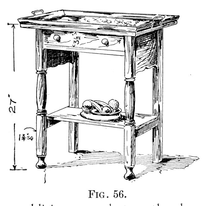
Serving Tray and Stand from Furniture for the Craftsman by Paul Otter
The table is 27 inches tall, so the legs divide into three basic sections of 9 inches each. As there are bun feet turned at the very bottom, and the top takes up three quarters of an inch, adjustments are made to each section to balance out the overall leg. Again, this is where a mock-up helps to figure out dimensions. Having a full-scale mock-up of the leg will also be useful when it comes time to turn the legs on the lathe.
Otter’s original drawing shows the lower shelf sitting on top of the lower stretchers. Although I wanted to create a piece that closely matches the original sketch, I did ultimately decide to alter the lower shelf. It’s okay as designed, and it does avoid cutting a few mortise and tenon joints, but looks less finished and not as strong as I’d like. I chose instead to set the lower shelf into the stretchers, making the shelf another stretcher and bracing the legs from side to side. Doing this also traps the shelf top and bottom, preventing it from cupping over time.
Another change I made was the design of the rear legs. It’s common among antique tables for the front legs to be designed with greater detailing than the back legs because the back legs of most tables remain against a wall and are pretty much unseen. As this is a serving stand rather than a table, it’s likely that it will be placed convenient to the dining table and not against a wall. If the front legs were fluted, reeded, or carved, I may well have chosen to keep the rears legs plain, but as the turning is fairly simple, I decided to turn all four.
Now that the basic plans are laid out, a materials list can be created. The list not only organizes your cutting and milling steps, but also helps you determine joinery details and find flaws.
The materials list is also your shopping list. We know we need four legs from thicker stock, and a fair amount of 4/4 stock for the shelf, top and aprons.
Tray Stand Materials:
- Tray Molding: 84" x 1.25 x .75
- 4 legs at: 1.5 x 1.5 x 26.25
- Stand Top: 12 x 20 x .75
- Lower Shelf: 7 x 16.25 x .75
- 2 Front/Back Aprons: 5 x 17 x .75
- 2 Side Aprons: 8.5 x 9 x .75
- 2 Lower Stretchers: 1.25 x 9 x .75
Don’t forget to consider every part. Drawer parts, knobs, drawer runners, hardware and fasteners all need to be decided upon and detailed in the materials list. Any parts that are irregularly shaped, like the apron sides, should be drawn out in scale to help you decide if they can be cut from a single board or glued up from smaller parts. This layout will also provide the template for cutting the shapes during assembly.
In our materials list, the drawer sides, back and runners still need to be decided, (keep in mind that the drawer front is cut from the front apron) and hardware specified. Once they are added, your materials list is finished.